Beschreibung
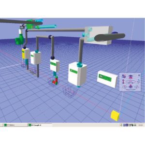
The Bridge is used when the bus-line is longer than a certain length. To connect the control-cable, two pairs of plug-connectors 25-pole for the supply line and the outgoing line are avaiable.
The two right ones are for the main-bus (comming from the central control unit), the two left ones are for the sub-bus (on-going system).
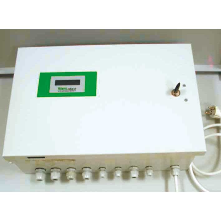
For the main-bus and the sub-bus the jumpers must be programmed.
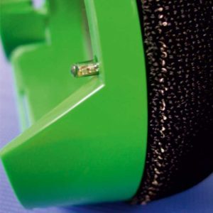
Below the DIP-switches there are five LEDs:
- LED-1 green – blinking and indicating the function
- LED-2 green – data transfer at the sub-bus
- LED-3 red – Can-bus malfunction
- LED-4 yellow – buffer overflow data transfer is not fast enough
- LED-5 green – data transfer at the main-bus
From address 112 on the bridge address will be set. The plug ST112 is a pick-off for the voltage of an additional power supply with sequence switch-off.
At ST13 an infrared light tube switch with a special function (e. G. a RSC for one-tube transfer) can be plugged in.